What is a stepper motor driver?
A stepper motor driver is an electronic device that is used to drive the stepper motor. By itself, it usually does nothing and must be used together with a controller like PoKeys57CNC.
There are a lot of different types of stepper motor drivers but in general, all do the same thing – move stepper motors.
Does a stepper motor need a driver?
Yes. Stepper motors require voltages and/or currents that the controller simply can’t produce. Therefore we need to use a stepper motor driver. This electronic device will transform our movement instructions from a controller into a sequence where the winding in the stepper motor will be turned on or off while still providing enough power to it.
All of this we of course be produced by a microcontroller driving a few FETs but the design and the programming would take time. Thankfully there are already existing solutions.
If we summarize, controllers are in general purely digital devices with low power output capability so we use an analog power stage as an interface between the digital (controller) and mechanic (motor) world.
How do stepper motor drivers work?
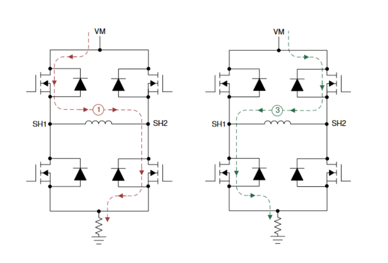
The basic task of the driver is to generate an appropriate signal from the input data to move the motor axis. The most common approach driving a stepper motor we call H-bridge. H-bridge circuits consist of 4 FET transistors with very low resistance between drain and source contact (RDSon) when inactive state. In general, we need at least two H-bridges since the motor has minimal two coils. With the combination of the right signal on FET’s gate, we control a current direction through the motor’s coil. Alternating excitation of two windings causes the motor axis to shift.
How do I choose a stepper motor driver?
When choosing the right driver for our system, we first need information about the motors we will be using. This is the main important information. We have to choose the driver according to the power stepper driver can deliver to the motor. For example, a bigger motor like NEMA 34 has a higher holding torque value than a smaller NEMA 17. That’s why NEMA 34 consume more current and we need a driver with higher amperage characteristic.
The next thing to consider is how and what would we like to control a driver. There is usually a setup for maximum current and micro-stepping, about which we will write in our own chapter of this article. We can have an option to set up a driver with jumpers or more sophisticated software that in most cases allows users to setup also other special options such as decay parameters, temperature protection limit, idle current, and so on.
Some drivers we can use only with a controller that generates step and direction signals. On the other hand, we can drive over different communication protocols.
Types of drivers
In general, there are two types of drivers. The constant voltage drivers (L/R drivers) and constant current drivers (chopper drivers).
- constant voltage drivers (L/R drivers):
- they are cheaper than constant current drivers
- use voltage to produce torque
- usually not efficient
- worse performance than chopper drivers
- constant current drivers (chopper drivers):
- more expensive
- more complex circuits
- use constant current to produce torque
- much better performance than the L/R drivers
The constant current drivers are almost always used since there are many ICs available and offer much better performance. You can find integrated circuits which already have integrated FETs, these are usually meant for lower currents (up to a couple of A). Since they are small a heat dissipation could be a problem. If we use external FETs, the maximum current is limited only to the characteristics of the selected FET and PCB design.
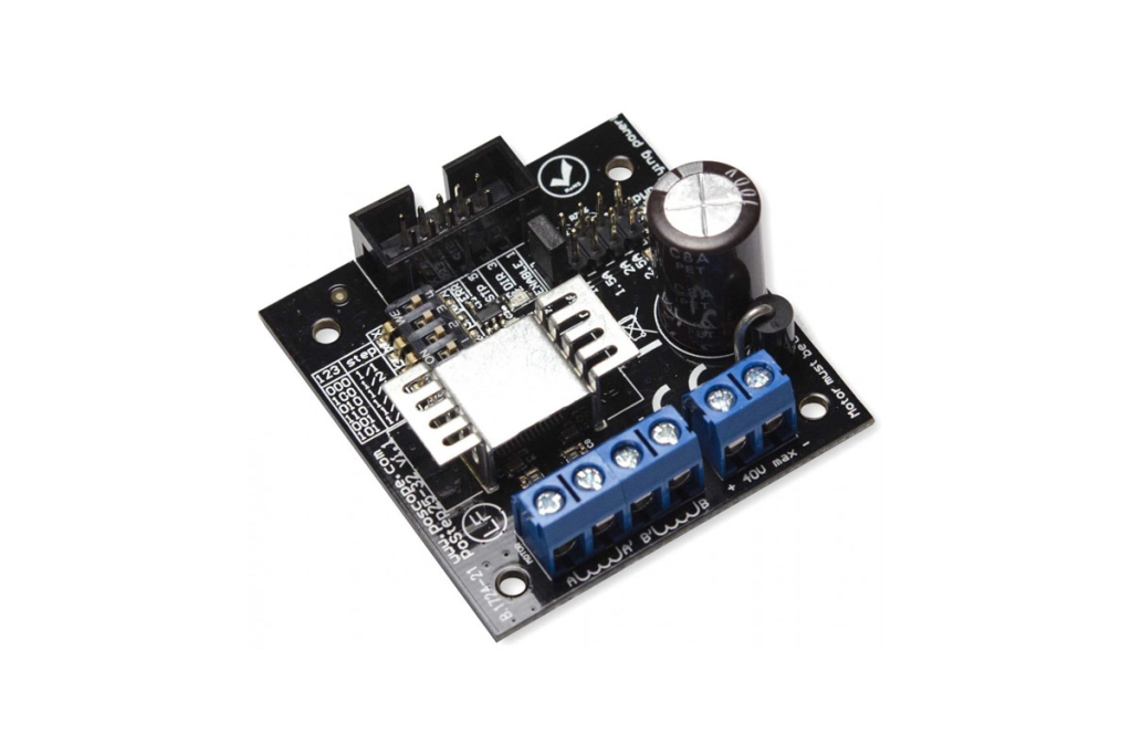
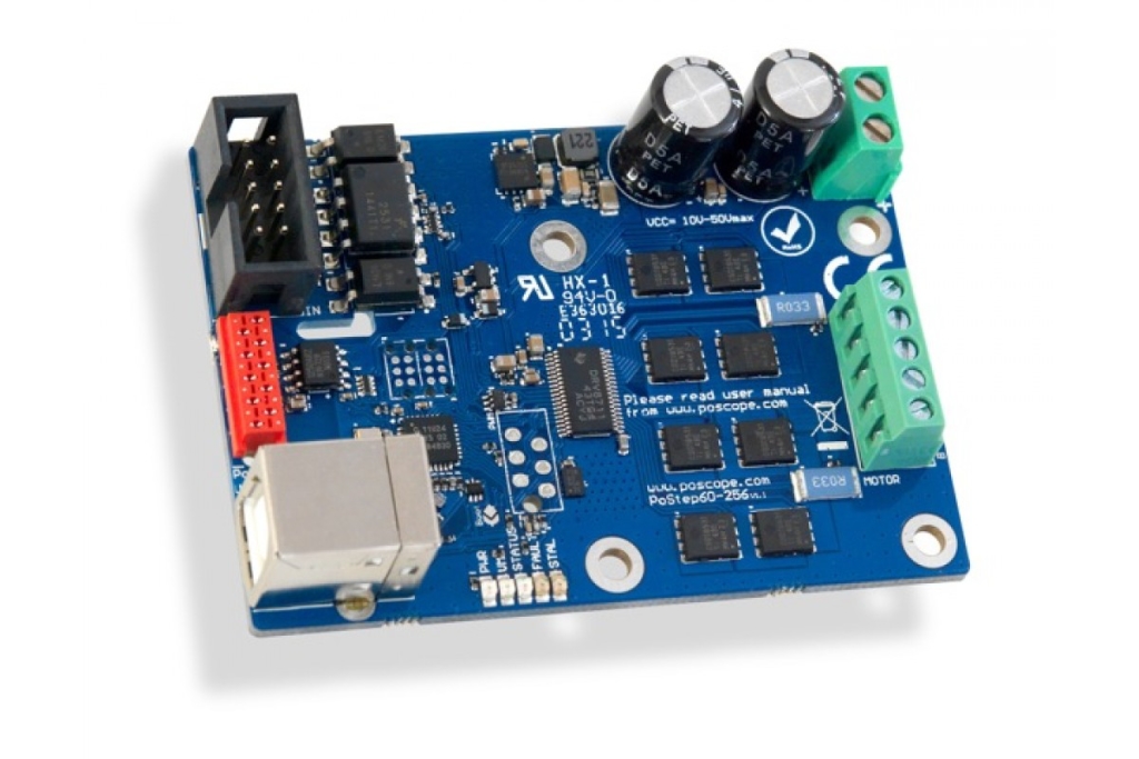
For example, the PoStep25-32 uses an integrated circuit that has integrated FETs and can provide up to 2.5A, unlike the PoStep60-256 which uses external FETs and can provide up to 6 Amps.
Micro-stepping
Stepper motors move in steps which is usually 1.8°, that is 200 steps per revolution. This can be a problem when we need small movements. One option would be to use some kind of transmission but there is also another way – micro-stepping. Micro-stepping means that we can have more than 200 steps per revolution and in turn have smaller movements. This option is already integrated in most ICs and can be configured by simply moving a jumper like on PoStep25-32.
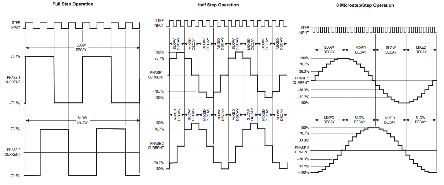
When driving stepper motors with full steps the output of the stepper motor driver looks like a square signal and produces rough movements. The bigger the micro-stepping the more the output signal looks like a sine wave and the stepper motor moves more smoothly. But there is a downside to this. With increasing micro-stepping value the torque drops a quite lot and if the value is too great it could happen that the motor can’t produce enough torque to even turn. Usually, 1/4, 1/8, or even 1/16 can produce satisfactory smooth movements while still producing enough torque.
The following image shows how the output changes when selecting different micro-stepping values. You can see that the output looks increasingly more like a sine wave.
So what do these micro-step values even mean?
Micro-stepping tells us how many micro-steps should a stepper make to produce one full step. The 1/1 value tells us that the stepper must make one micro-step to produce one full step (so there is no micro-stepping). Value of 1/2 is called a half step and tells us that the stepper motor must make 2 micro-steps for one full step. This means that the stepper motor should make 400 steps for one full revolution. A value of 1/8 will tell us that the motor should make 8 micro-steps for one full step and 1600 steps for one full revolution. The same principle applies for all of the micro-stepping values.
How to drive the stepper motor driver?
Most stepper motor drivers accept a step and direction input signals. That means we need only two signals for each driver. The step signal is used for making steps and looks like a PWM signal. Each pulse means that the stepper will move for one step (or micro-step). The direction signal is used to signal in which direction (CW or CCW) will the stepper turn. There are applications where we use stepper motor independently and so appropriate control of the driver is a standard communication protocol such as MODBUS, USB, or I2C.

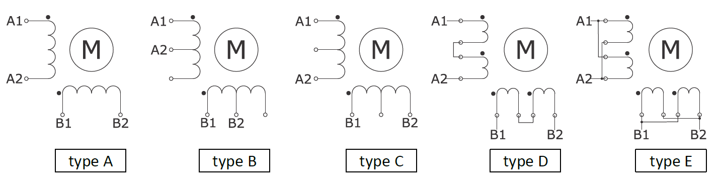
How do you wire up the stepper motor?
if you researched stepper motors you may have noticed that they have a different number of connecting wires. Most common are motors with two coil windings, 4 wires. In the picture below you can see a different wiring option for motors with 4, 6, or 8 wires.
Conclusion
We have found out that the stepper motor driver is a must-have if our design requires the use of a stepper motor since the controller can’t produce enough current and enough high voltage. There are different types but the chopper drivers offer the best performance. Also, the micro-stepping offers a great solution at first sight but produces a problem of decreased torque. It is still extremely useful but we must use it properly. There are a lot of different ICs available for driving the stepper motor and many already made solutions like PoStep25-32 and PoStep60-256 which provide plug and play solutions and are easy to use.
And if you would like to learn more here is a great starting point.