What is CNC tool setter
Most hobby and semi-professional machines do not have an ATC spindle. That means that the tools can not be changed quickly and tool change requires loosening the nut with the collet and change tool. The before-mentioned part is still quite simple and quick, but the main problem is that now with the new tool you don’t know the length of the tool nor can the length be stored in the tool table since manually changing tools is not repeatable.
To solve that problem, the first and most commonly used option is to touch off the tool manually. You can do that with the help of a gage block or dowel pin on the known reference surface. That is quite repeatable and easy but also time-consuming as well as prone to errors.
The better option is to automate that process with the CNC tool setter and a reliable probing routine. That can automatically measure the tool length and apply the right offset so you can resume machining quickly after changing the tool.
Benefits of the automatic tool setter
Sometimes additional operations on a CNC are avoided only because tool change is necessary and manually changing tools is time-consuming. Errors can also occur with tools that are not measured or measured incorrectly.
Tool length measuring automation greatly simplifies machining, saving time with a lot less manual labor and quicker production of finished parts. So cnc tool setter is the way to go with that process.
Difference between CNC tool setter and probe
In a previous blog post, we described mach4 probing with a probe tool. Probing in that sense is used when you want to locate the part that you are about to machine. That means that you tell the machine where is the zero point in the machine XYZ coordinates where the stock is located.
Tool setting with a CNC tool setter is the process of measuring the length of the tool. The zero point should also coincide with the zero point of the stock. If tool length is not set properly the tool can dig too deep into the material and break the tool in the worst case. If you are lucky the tool will not cut the material at all since its length is set too long.
How to connect the CNC tool setter with PoKeys
To connect the CNC tool setter device to the PoKeys, in our case the PoKeys57CNC, you first need to find a free pin that is not already used for anything else. The easiest option is to use the pin for the probe, which is located on the limit switches connector. If you are already using the probe, then you have to find the other available pin, but you can not use the limit pins for probing. The probing pin must be labeled with a grey box as “PIN xx” on page 11 of the PoKeys57CNC manual.
The easiest way to connect the probe is with AdapterPNPN. If you are using PNP or NPN probe or even if it is just a switch, connecting it to AdapterPNPN and PoKeys57CNC is only a matter of connecting a few wires and setting jumpers to the appropriate side.
PNP sensor’s signal wire should be connected to PNP input on screw terminal. It does not matter if the sensor wire is NO (normally open) or NC (normally closed) contact. The benefit of NC wiring is that the error in circuitry and wiring is detected since the signal is not present. If for instance, you cut the sensor cable, the error can be triggered. The jumper has to be set accordingly to the PNP side if using PNP sensor.
In case you use NPN sensor, you should connect sensor wire to the NPN input on the terminal, and set the jumper on the NPN side. Again, NO or NC wiring does not matter here, it is managed in the software settings where you can invert the signal if needed.
In case you are using ordinary switch contacts, you can wire switch between VCC and PNP terminal and set the jumper to PNP. Or you can wire the switch between NPN and GND with the jumper set to the NPN. You still have to connect the power supply in order for the adapter to work even though switches do not need supply in order to function.
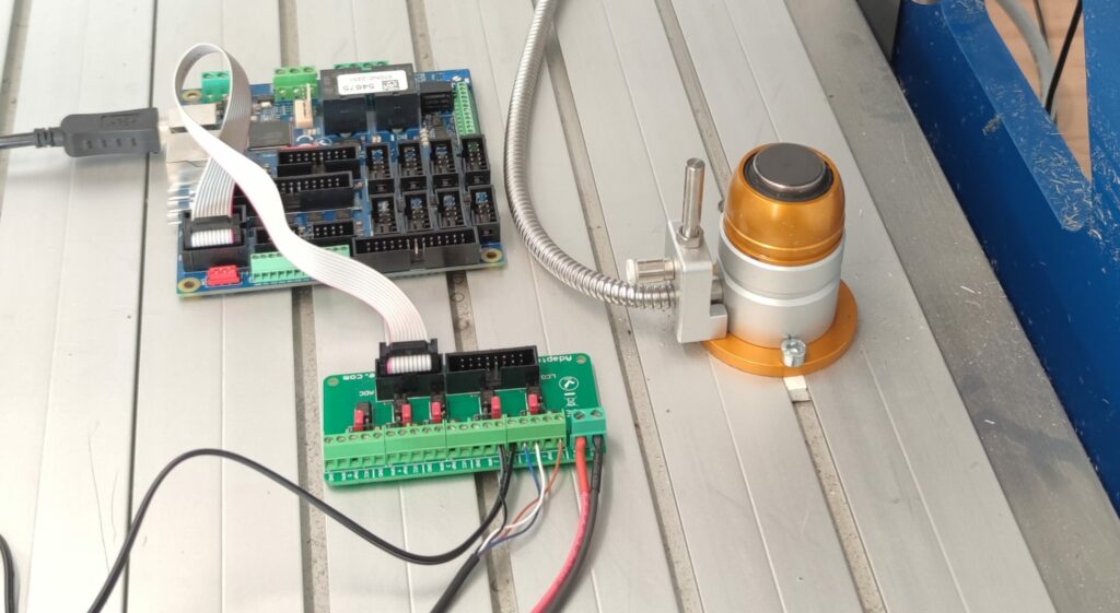
In our case, the CNC tool setter has two normally closed contacts, one for tool measuring and one for over-travel. We connected in VCC and PNP terminal and set the jumper to PNP side on input number 2. LED is on all the time since the sensor is NC, but when we trigger the sensor LED turns off.
The wiring can be checked in the PoKeys app with a data logger. PoKeys app has to be opened and the right device selected, then the data logger tab clicked. A new window will open and on the right row with the input pin, the state of the pin will change when the probe is activated. The state of the pin could also be verified in Mach4 in the “Diagnostics” tab under “PoKeys plugin – PoLabs”. There are all the pins visible with the colour change when the state of the pin changes.
How to configure Mach4 for automatic cnc tool setter
It is of the utmost importance that the latest version of the Mach4 is installed along with the latest version of the PoKeys plugin. Multiple probing works only with newer versions of the software and reliability is also greater.
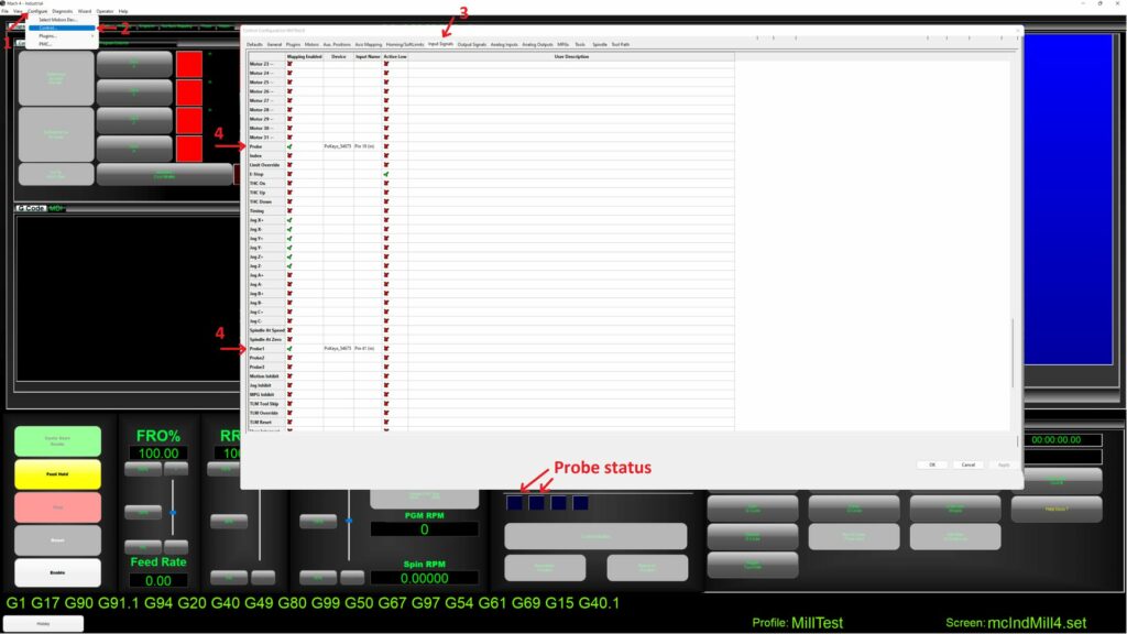
The setup for probing is simple, the only thing that has to be configured is the input signal in Mach4 configuration under “Configure” -> “Controll…”. In the “Input signals,” the Probe Mapping has to be enabled and the right pin chosen. As mentioned before, PoKeys “Pin xx” has to be selected for probing. The selected “Device” is PoKeys_[serial number] and the input name is the selected pin. To invert the pin “Active low” can be selected.
If you already have one probe for the XYZ probing, then you can connect the CNC tool setter to the probe1 or any other probe.
That is all the configuration in Mach4. You can check the tool setter pin state in GUI, where in case of probe triggering the blue rectangle changes colour. It is always the best practice to test the reliability before serious use.
How to test and touch off tools with a CNC tool setter and manual programming
The easiest way to test the probe is to first trigger the probe manually multiple times and observe the behavior of the blue square in the Mach4 GUI. If it reliably changes color then wiring is most probably OK. The next step is to start testing automatic measurements.
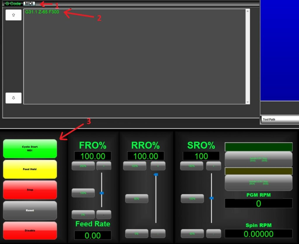
It is recommended to start with manually writing the following g-code line in the MDI and then execute that line. The g-code for probing is G31 if using the probe number 0. For probe number 1 the g-code is G31.1, for probe number 2 it is G32.2, and so on.
The parameters for the g-code are the Z distance that the probe or tool will travel to while waiting for the signal. The last parameter is feed rate, which can be initially set to a low value, around 20mm/min to be save. It can be later increased of course.
The g-code for probing with probe 0 to the Z value of -10mm and feed of 20mm/min is “G31 Z-10 F20”. When the line is copied into the MDI window, you can “Cycle Start MDI” to run the line. Try to safely trigger the tool setter or probe to see if the machine stops.
When manually using probing g-code, it is also possible to switch from absolute to relative coordinates with G90 (for incremental or relative positioning), then the Z value in the “G31 Z-10 F20” will be interpreted from the current position and the tool will travel 10mm in the negative direction from where it is. It is very important to switch back to G91 after probing to use the absolute positioning again.
In our case, the tool setter is positioned on the table of the machine. The main goal was to establish a routine that would touch off tools during machining after a manual tool change. The idea is that after you changed the tool the offset would be measured and the work zero would stay where it is. That way the process is reliable and a lot of time is saved.
Automatic routine to touch off tools
In case the tool setter has a fixed position on the table, the position must somehow be known to the controller. The most reliable way is to set up the homing routine in case it is not already set up. Then the position of the tool setter has to be manually measured, the easiest way is to jog the machine around and check the machine coordinates. The most important ones are X and Y coordinates since the Z will be probed.
Afterwards, for probing the tool length the following g-code can be run:
M5 (turn off spindle)
G43 H1 (tool length offset set to tool 1)
G53 G1 Z0 F3000 (move Z-axis to zero away from the table)
G53 G1 X-38.5 Y-13.1 F3000 (move to tool setter location in X and Y)
M49 (disable feed rate override)
G53 G31.1 Z-65 F300 (probe command)
G10 L1 P1 Z#5073 (apply new tool offset from Mach4 variable #5073 – probe machine coordinate)
M48 (enable feed rate override)
The idea with the upper g-code is to use the machine home coordinate of the probe to set as a tool offset so it is mandatory to run homing routine before upper g-code. When the tool length is measured the work offsets (G54, G55, etc.) can be set up afterward and not before.

With the appropriate coordinate input, the spindle should get right above the tool setter. For your machine, the right coordinates have to be applied. After the machine is in the right spot, the g-code for probing can be input to measure the tool length offset.
Is an automatic tool setter really necessary?
The tool setter greatly simplifies the CNC machining process and makes it more reliable. Conventional methods of setting up tools still work and are robust, but they are also time-consuming and prone to human errors. And since the tool setter have become cheaper and more readily available there is no reason that machinists would not use them.
Even though the setup might look complicated at first glance, it is quite quick and simple but more importantly, it pays off to invest time into learning new things as well as do some maintenance and improvements to your machine. We recently also made a big improvement to our machine when we eliminated cnc chatter when doing heavier machining. We upgraded the Z axis for much better rigidity and performance.
How to measure tool length without a CNC tool setter
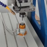
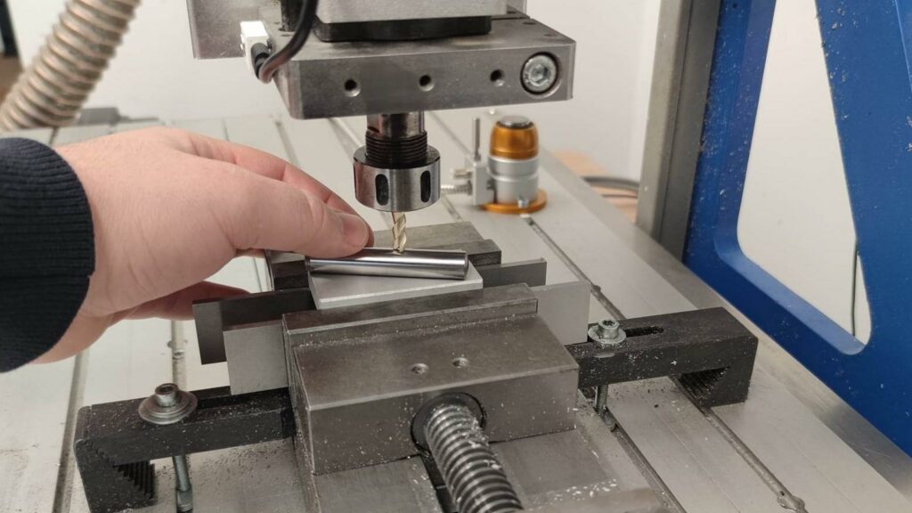
The conventional method of setting up tools is using a dowel pin or other precision gauge. The best practice is to lower the tool more than the height of the gauge. Then you slowly retract it until the gauge is able to slip under the tool. That way you prevent crashing into the gauge and chipping the tool. The height of the gauge is then inserted into the Mach4 and the offset is automatically calculated.
You can also position the tool setter on the workpiece to measure tools. That is usually the case on hobby machines and the tool setter is the simple metal plate with the continuity cable connected between the tool and the setter plate.
There are surely other ways to measure tool lengths that I did not mention. I hope we gave you some insight into tool length measuring.