This tutorial will explain how to set the motor and soft limits of your machine.
Soft limits (sometimes also program limits term is used) will stop machine motion when motor limit values of specific machine axis are achieved (without any limit switch activation). Soft limits will stop the machine in a soft stop fashion, meaning axis motors will use deceleration – hence the name, soft limits.
First, you need to configure step per unit values and limit switch inputs of the controller:
How to set Steps Per Unit values in PlanetCNC TNG software
How to configure limit switch inputs of the controller in PlanetCNC TNG software
Configuring motor and soft limits
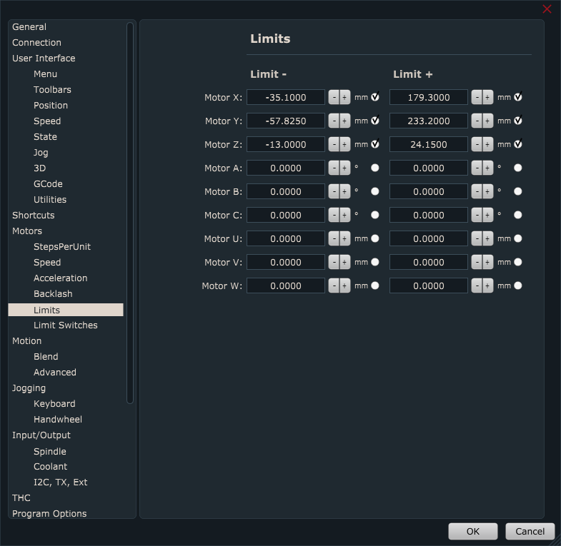
You can configure motor limit values for each axis.
Limit- value sets limitation of axis movement in a negative direction
Limit+ value sets limitation of axis movement in a positive direction
Step 1:
First, we need to set all machine and tool offsets values to zero.
Work offset should be set to zero with the command “Machine/Work Position/Offset->To Zero”.
Tool offset should be set to zero with the command “Machine/Tool Offset -> To Zero”.
Step 2:
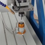
Now we need to choose where the machine’s zero position is. Usually, the machine works in work position coordinates and it is not really important where machine zero is. What is important is that it is always in the same position. I will put some tape to mark it so that you will see it better on the image:
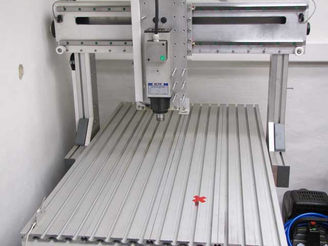
The tool is put in a spindle and the machine is jogged to this position. Use a tool with normal length, not too short, not too long. Be careful not to crush the tool into the machine table when you descent Z-axis. You can just loosely tighten the tool in the spindle and if an accident happens nothing will be damaged.

This position should be machine zero. The command for zeroing machine position is in the menu: “Machine/Machine Position ->To Zero”.
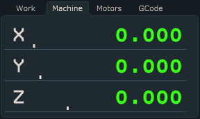
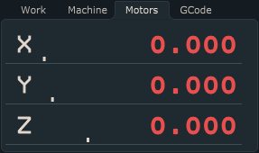
After using the “To Zero” feature you will notice that values under the Machine and Motors tab in the coordinate position display will be zero for all axes:
Step 3:
Slowly jog Z axis up until Z+ limit switch is hit and the machine stops. Step jog in the opposite direction so that limit switch is released and write down Z+ axis machine position.
Slowly jog X-axis in the positive direction until the X+ limit switch is hit and the machine stops. Step jog in the opposite direction so that limit switch is released and write down X+ axis machine position.
Slowly jog X-axis in the negative direction until X- limit switch is hit and the machine stops. Step jog in the opposite direction so that the limit switch is released and write down the X-axis machine position.
Slowly jog Y-axis in the positive direction until the Y+ limit switch is hit and the machine stops. Step jog in the opposite direction so that the limit switch is released and write down the Y+ axis machine position.
Slowly jog Y-axis in the negative direction until the Y- Y-limit switch is hit and the machine stops. Step jog in the opposite direction so that the limit switch is released and write down the Y-axis machine position.
PLEASE NOTE: Motor limit values obtained above are just an example of how you can obtain and define them. Motor limit values can be any values that suit your machine and application.
Step 4:
Now insert values that you have previously written down(X+, X-; Y+, Y-; Z+) into Limit windows. If we want motors to stop when limits are reached, we must enable the radio button for the desired axis. By doing this, we now set soft limits:
Step 5: Enable/Disable soft limits
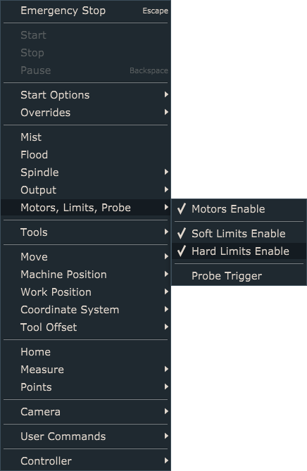
To enable soft limit settings, you need to make sure that they are enabled under Machine/Motors, Limits, Probe/Soft Limits Enable
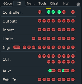
To observe Soft Limits enable/disable state, you can do that by observing:
-Machine/Motors, Limits, Probe/Soft Limits Enable menu. Checked for enabled, unchecked for disabled
-SL light under IO tab which will toggle according to the above settings. Green when soft limits are enabled, and red when they are disabled